
Roll
Length
25 to 50 m: ± 0,5 m
50 to 100 m: ± 1 m
100 to 200 m: ± 1,5 m
> 200 m: ± 2 m
Width
0 à 200 m: ± 1 mm
201 to 600 mm: ± 2 mm
601 to 1000 mm: ± 4 mm
1001 to 2000 mm: ± 6 mm
2001 to 3000 mm: ± 7 mm
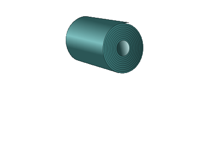
Roll / Stock Piece "as is"
Length
0 to 10 m: ± 0,5 m
10 to 25 m: ± 1 m
25 to 50 m: ± 2 m
>50 m: ± 3 m
Width
0 to 200 m: ± 1 mm
201 to 600 mm: ± 2 mm
601 to 1000 mm: ± 4 mm
1001 to 2000 mm: ± 6 mm
2001 to 3000 mm: ± 7 mm
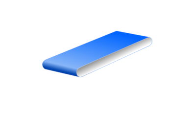
Open Belt
Length
0 to 1 m: ± 5 mm
1 to 3 m: ± 10 mm
3 to 7 m: ± 20 mm
>7 m: ± 0,3 %
Width
0 to 200 m: ± 1 mm
201 to 600 mm: ± 2 mm
601 to 1000 mm: ± 4 mm
1001 to 2000 mm: ± 6 mm
2001 to 3000 mm: ± 7 mm
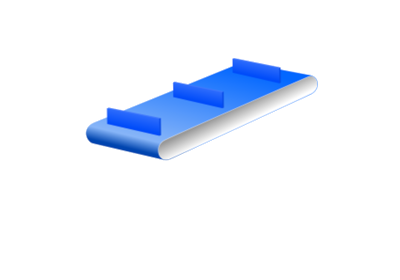
Fabricated Belt
Length
0 to 1 m: for a width ≤ 0,5m: ± 15 mm, if width >0,5 m: ± 10 mm
1 à 3 m: for a width ≤ 0,5m: ± 25 mm, if width >0,5 m: ± 20 mm
3 à 7 m: for a width ≤ 0,5m: ± 35 mm, if width >0,5 m: ± 30 mm
>7 m : ± 0,5 %
Width
0 to 200 mm: ± 1 mm (with FPS [sealed edges]: +2/-3 mm)
201 to 600 mm: ± 2 mm (with FPS [sealed edges]: +2/-5 mm)
601 to 1000 mm: ± 4 mm (with FPS [sealed edges]: +2/-6 mm)
1001 to 2000 mm: ± 6 mm (with FPS [sealed edges]: +2/-8 mm)
2001 to 3000 mm: ± 7 mm
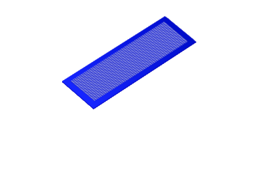
Mesh Belt
Length
0 to 1 m: ± 10 mm
1 to 3 m: ± 20 mm
3 to 7 m: ± 30 mm
>7 m: ± 0,5 %
Width
0 to 200 mm: ± 2 mm
201 to 600 mm: ± 3 mm
601 to 1000 mm: ± 6 mm
1001 to 2000 mm: ± 8 mm
2001 to 3000 mm: ± 10 mm
Fabricated Mesh Belt
Length
0 to 1 m : ± 10 mm
1 to 3 m : ± 20 mm
3 to 7 m : ± 40 mm
>7 m : ± 0,6 %
Width
0 to 200 mm : ± 2 mm
201 to 600 mm: ± 4 mm
601 to 1000 mm: ± 8 mm
1001 to 2000 mm: ± 12 mm
2001 to 3000 mm: ± 14 mm
General Tolerances for Belts
Total thickness: ± 0,1 mm par pli
Weight: ± 10 %
Coefficient of friction on steel slider bed: ± 20 %
Breaking strength: -10 % / + 20 %
k1% tensile force : -10 % / + 20 %
Max. tensile force: -10 % / + 20 %
Accessories and Fabrication
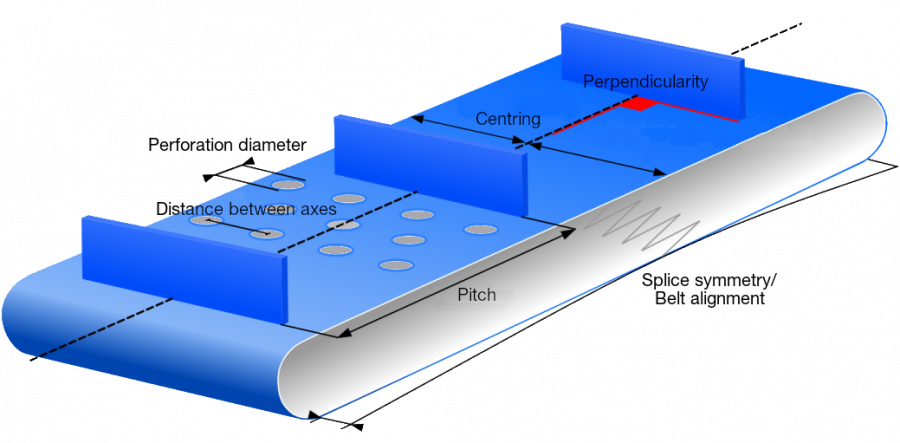
Pitch: ± 2 mm (non-accumulative)
Perpendicularity: 2 mm for width ≤ 200 mm, 1 % for width >200 mm
Centring: ± 2 mm
Distance between axes: ± 2 mm non cumulable
Length: ± 2 mm
Height: ± 10 %
Splice symmetry and belt misalignment: 0,1 % de la longueur
Perforation diameter (except jointing area) : ± 0,5 mm for ⌀ ≤ 20 mm, ± 1 mm for ⌀ > 20 mm
Determining the adjustment range for belt tensioning
The adjustment range on the conveyor must be at least 1,5% of the total length of the belt. Hence,for a belt with a total length of 10 m, the tensioning system of the conveyor must at least have an adjustment range of 75 mm.

Determining the length of a belt
La longueur d'une bande doit être mesurée avec le système de tension sorti au 1/3. Pour passer la bande, il faudra rentrer les tendeurs entièrement. Il restera ensuite 2/3 de course de réglage pour tendre la bande.
Taking into account the fabrication tolerances, it is essential to check the available adjustment range on the conveyor beforehand. If your adjustment range is less than 1,5 % of the belt length, please let us know.
